ASTM B139 / B139M
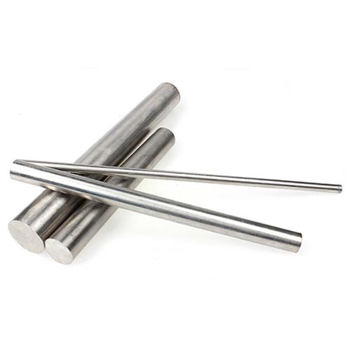
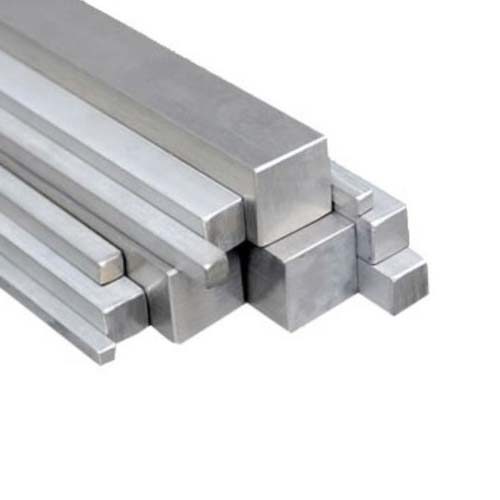
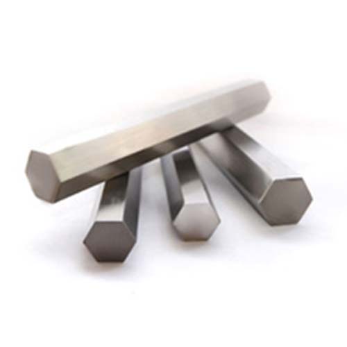
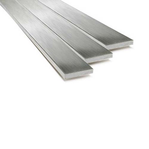
This specification establishes the requirements for phosphor bronze rod, bar, and shapes. Units—The values stated in inch-pound units or SI units are to be regarded separately in the standard. Within the text, the SI values are given in brackets. The values stated in each system are not exact equivalents; each system of units is independent of the other. Combining values from the two systems may result in nonconformance with the specification.
Chemical Properties
| Copper Alloy UNS No. | Tin | Phosphorus | Iron, max | Lead | Zinc | Copper |
|---|---|---|---|---|---|---|
| C51000 | 4.2–5.8 | 0.03–0.35 | 0.10 | 0.05 max | 0.30 max | remainder |
| C52100 | 7.0–9.0 | 0.03–0.35 | 0.10 | 0.05 max | 0.20 max | remainder |
| C52400 | 9.0–11.0 | 0.03–0.35 | 0.10 | 0.05 max | 0.20 max | remainder |
| C53400 | 3.5–5.8 | 0.03–0.35 | 0.10 | 0.8–1.2 | 0.30 max | remainder |
| C54400 | 3.5–4.5 | 0.01–0.50 | 0.10 | 3.5–4.5 | 1.5–4.5 | remainder |
Mechanical Properties, inch-pound
| Temper Designation, Code | Material Conditions | Diameter or Distance Between ParallelA Surfaces, in. | Tensile Strength, min, ksi | Yield Strength at 0.5 % Extension Under Load, min, ksi | Elongation min, %B |
|---|---|---|---|---|---|
| Copper Alloy UNS No. C51000 | |||||
| O60 | soft anneal | rod: round under 1⁄4 | 40 | 58 | ... |
| H04 | hard | rod: round under 1⁄4 | 80 | 128 | ... |
| round and hexagonal: | |||||
| 1⁄4 to 1⁄2 , incl | 70 | ... | 13 | ||
| over 1⁄2 to 1, incl | 60 | ... | 15 | ||
| over 1 | 55 | ... | 18 | ||
| bar: square and rectangular: | |||||
| 1⁄4 to 3⁄8 , incl | 60 | ... | 10 | ||
| over 3⁄8 | 55 | ... | 15 | ||
| H08 | spring | rod: round: | |||
| 0.026 to 1⁄16 , incl | 115 | ... | ... | ||
| over 1⁄16 to 1⁄8 , incl | 110 | ... | ... | ||
| over 1⁄8 to 1⁄4 , incl | 105 | ... | 3.5 | ||
| over 1⁄4 to 3⁄8 , incl | 100 | ... | 5.0 | ||
| over 3⁄8 to 1⁄2 , incl | 90 | ... | 9.0 | ||
| Copper Alloy UNS No. C52100 | |||||
| O60 | soft anneal | rod: round under 1⁄4 | 53 | 68 | ... |
| H04 | hard | rod: round under 1⁄4 | 105 | 150 | ... |
| round and hexagonal: | |||||
| 1⁄4 to 1⁄2 , incl | 85 | ... | 12 | ||
| over 1⁄2 to 1, incl | 75 | ... | 15 | ||
| over 1 | 60 | ... | 20 | ||
| bar: square and rectangular: | |||||
| 1⁄4 to 3⁄8 , incl | 68 | ... | 10 | ||
| over 3⁄8 | 60 | ... | 15 | ||
| Copper Alloy UNS No. C52400 | |||||
| O60 | soft anneal | rod: round under 1⁄4 | 60 | 75 | ... |
| H04 | hard | rod: round under 1⁄4 | 105 | 160 | ... |
| round and hexagonal: | |||||
| 1⁄4 to 1⁄2 , incl | 95 | ... | 10 | ||
| over 1⁄2 to 1, incl | 85 | ... | 12 | ||
| over 1 | 70 | ... | 15 | ||
| bar: square and rectangular: | |||||
| 1⁄4 to 3⁄8 , incl | 76 | ... | 10 | ||
| over 3⁄8 | 70 | ... | 15 | ||
| Copper Alloy UNS Nos. C53400 and C54400 | |||||
| H04 | hard | rod: round and hexagonal: | |||
| 1⁄16 to 1⁄4 , incl | 65 | ... | 8 | ||
| over 1⁄4 to 1⁄2 , incl | 60 | ... | 10 | ||
| over 1⁄2 to 1, incl | 55 | ... | 12 | ||
| over 1 | 50 | ... | 15 | ||
| bar: square and rectangular: | |||||
| 1⁄4 to 3⁄8 , incl | 55 | ... | 10 | ||
| over 3⁄8 | 50 | ... | 15 | ||
Note:
A For rectangular bar, the Distance Between Parallel Surfaces refers to thickness.
B In any case, a minimum gage length of 1 in. shall be used.
Mechanical Properties, [SI]
| Temper Designation, Code | Material Conditions | Diameter or Distance Between ParallelA Surfaces, in. | Tensile Strength, min, ksi | Yield Strength at 0.5 % Extension Under Load, min, ksi | Elongation min, %B |
|---|---|---|---|---|---|
| Copper Alloy UNS No. C51000 | |||||
| O60 | soft anneal | rod: round under 6 | 275 | 400 | ... |
| H04 | hard | rod: round under 6 | 550 | 880 | ... |
| round and hexagonal: | |||||
| 6 to 12 incl | 485 | ... | 13 | ||
| 12 to 25 incl | 415 | ... | 15 | ||
| over 25 | 380 | ... | 18 | ||
| bar: square and rectangular: | |||||
| 6 to 9 incl | 415 | ... | 10 | ||
| over 9 | 380 | ... | 15 | ||
| H08 | spring | rod: round: | |||
| 0.065 to 1.6 incl | 790 | ... | ... | ||
| over 1.6 to 3 incl | 760 | ... | ... | ||
| over 3 to 6 incl | 725 | ... | 3.5 | ||
| over 6 to 9 incl | 690 | ... | 5.0 | ||
| over 9 to 12 incl | 620 | ... | 9.0 | ||
| Copper Alloy UNS No. C52100 | |||||
| O60 | soft anneal | rod: round under 6 | 365 | 470 | ... |
| H04 | hard | rod: round under 6 | 720 | 1030 | ... |
| round and hexagonal: | |||||
| 6 to 12 incl | 585 | ... | 12 | ||
| over 12 to 25 incl | 515 | ... | 15 | ||
| over 25 | 415 | ... | 20 | ||
| bar: square and rectangular: | |||||
| 6 to 9 incl | 470 | ... | 10 | ||
| over 9 | 415 | ... | 15 | ||
| Copper Alloy UNS No. C52400 | |||||
| O60 | soft anneal | rod: round under 6 | 415 | 515 | ... |
| H04 | hard | rod: round under 6 | 725 | 1100 | ... |
| round and hexagonal: | |||||
| 6 to 12 incl | 655 | ... | 10 | ||
| over 12 to 25 incl | 585 | ... | 12 | ||
| over 25 | 480 | ... | 15 | ||
| bar: square and rectangular: | |||||
| 6 to 9 incl | 525 | ... | 10 | ||
| over 9 | 480 | ... | 15 | ||
| Copper Alloy UNS Nos. C53400 and C54400 | |||||
| H04 | hard | rod: round and hexagonal: | |||
| 1.6 to 6 incl | 450 | ... | 8 | ||
| over 6 to 12 incl | 415 | ... | 10 | ||
| over 12 to 25 incl | 380 | ... | 12 | ||
| over 25 | 345 | ... | 15 | ||
| bar: square and rectangular: | |||||
| 6 to 9 incl | 380 | ... | 10 | ||
| over 9 | 345 | ... | 15 | ||
Note:
A For rectangular bar, the Distance Between Parallel Surfaces refers to thickness.
B In any case, a minimum gage length of 25mm shall be used.


