ASTM B98 / B98M
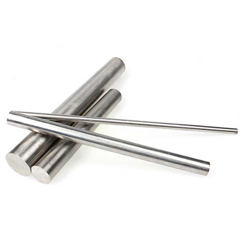
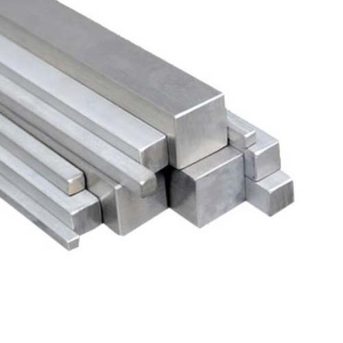
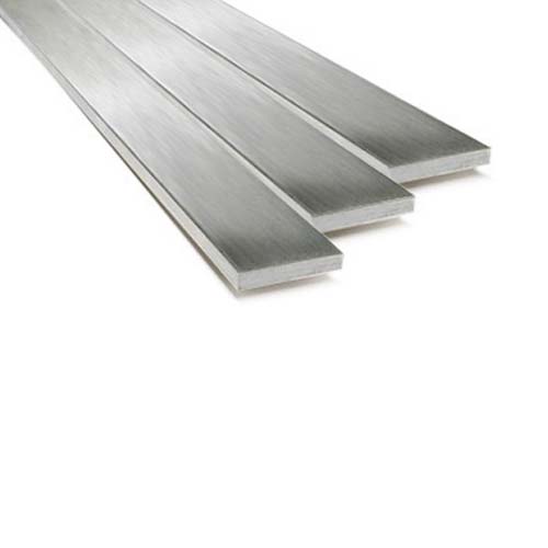
This specification establishes requirements for copper silicon rod, bar, and shapes for UNS Alloys C65100, C65500, and C66100.The values stated in inch-pound units or SI units are to be regarded separately as standard.Within the text, SI units are shown in brackets. The values in each system are not exact equivalents; therefore, each system shall be used independently of the other. Combining values from the two systems may result in nonconformance with the specification.
Chemical Properties
| UNS Designation | Copper (Includes silver) |
Lead | Iron | Zinc | Manganese | Silicon | Nickel (includes cobalt) |
|---|---|---|---|---|---|---|---|
| C65100 | remainder | 0.05 | 0.8 | 1.5 | 0.7 | 0.8–2.0 | ... |
| C65500 | remainder | 0.05 | 0.8 | 1.5 | 0.50–1.3 | 2.8–3.8 | 0.6 |
| C66100 | remainder | 0.20–0.8 | 0.25 | 1.5 | 1.5 | 2.8–3.5 | ... |
Mechanical Properties
| Temper Designation Standard Name | Material Conditions | Diameter or Distance Between ParallelA Surfaces, in. | Tensile Strength, min, ksi | Yield Strength at 0.5 % Extension Under Load, min, ksi | Elongation in 4 x Diameter or Thickness of Specimen, min, %B |
|---|---|---|---|---|---|
| Copper Alloy UNS No. C65100 Rods, Bars, and Shapes | |||||
| O60 | Soft anneal | All forms, all sizes | 40 | 12 | 30 |
| H02 | Half-hard | Rods: | |||
| Up to 1⁄2, incl | 55 | 20 | 11 | ||
| Over 1⁄2 to 2, incl | 55 | 20 | 12 | ||
| Bars and shapes | C | C | C | ||
| H04 | Hard | Rods: | |||
| Up to 1⁄2, incl | 65 | 35 | 8 | ||
| Over 1⁄2 to 2, incl | 65 | 35 | 10 | ||
| Bars and shapes | C | C | C | ||
| H06 | Extra-hard | Rods: | |||
| Up to 1⁄2, incl | 85 | 55 | 6 | ||
| Over 1⁄2 to 1, incl | 75 | 45 | 8 | ||
| Over 1 to 11⁄2, incl | 75 | 40 | 8 | ||
| Copper Alloy UNS Nos. C65500 and C66100 Rectangular Bars | |||||
| O60 | Soft anneal | All sizes | 52 | 15 | 35 |
| H04 | Hard | ||||
| Up to 1, incl | 65 | 38 | 20 | ||
| Over 1 to 11⁄2, incl | 60 | 30 | 25 | ||
| Over 11⁄2 to 3, incl | 55 | 24 | 27 | ||
| Copper Alloy UNS Nos. C65500 and C66100 Rods, Square Bars, and Shapes | |||||
| O60 | Soft anneal | All forms, all sizes | 52 | 15 | 35 |
| H01 | Quarter-hard | All forms, all sizes | 55 | 24 | 25 |
| H02 | Half-hard | Rods and square bars: | |||
| Up to 2, incl | 70 | 38 | 20 | ||
| Shapes | C | C | C | ||
| H04 | Hard | Rods and square bars: | |||
| Up to 1⁄4, incl | 90 | 55 | 8 | ||
| Over 1⁄4 to 1, incl | 90 | 52 | 13 | ||
| Over 1 to 11⁄2, incl | 80 | 43 | 15 | ||
| Over 11⁄2 to 3, incl | 70 | 38 | 17 | ||
| Over 3 | C | C | C | ||
| Shapes | C | C | C | ||
| H06 | Extra-hard | Rods: up to 1⁄2, incl | 100 | 55 | 7 |
Note:
A For rectangular bar, the Distance Between Parallel Surfaces refers to thickness.
B In any case a minimum gage length of 1 in. shall be used.
C As agreed upon between manufacturer and purchaser.
| Temper Designation Standard Name | Material Conditions | Diameter or Distance Between ParallelA Surfaces, in. | Tensile Strength, min, MPa | Yield Strength at 0.5 % Extension Under Load, min, MPa | Elongation, min, %B |
|---|---|---|---|---|---|
| Copper Alloy UNS No. C65100 Rods, Bars, and Shapes, | |||||
| O60 | Soft anneal | All forms, all sizes | 275 | 85 | 30 |
| H02 | Half-hard | Rods: | |||
| Up to 12, incl | 380 | 140 | 11 | ||
| Over 12 to 50, incl | 380 | 140 | 12 | ||
| Bars and shapes | C | C | C | ||
| H04 | Hard | Rods: | |||
| Up to 12, incl | 450 | 240 | 8 | ||
| Over 12 to 50, incl | 450 | 240 | 10 | ||
| Bars and shapes | C | C | C | ||
| H06 | Extra-hard | Rods: | |||
| Up to 12, incl | 585 | 380 | 6 | ||
| Over 12 to 25, incl | 515 | 310 | 8 | ||
| Over 25 to 38, incl | 515 | 275 | 8 | ||
| Copper Alloy UNS Nos. C65500 and C66100 Rectangular Bars | |||||
| O60 | Soft anneal | All sizes | 360 | 105 | 35 |
| H04 | Hard | ||||
| Up to 25, incl | 450 | 260 | 20 | ||
| Over 25 to 38, incl | 415 | 205 | 25 | ||
| Over 38 to 75, incl | 380 | 165 | 27 | ||
| Copper Alloy UNS Nos. C65500 and C66100 Rods, Square Bars, and Shapes | |||||
| O60 | Soft anneal | All forms, all sizes | 360 | 105 | 35 |
| H01 | Quarter-hard | All forms, all sizes | 380 | 165 | 25 |
| H02 | Half-hard | Rods and square bars: | |||
| Up to 50, incl | 485 | 260 | 20 | ||
| Shapes | C | C | C | ||
| H04 | Hard | Rods and square bars: | |||
| Up to 6, incl | 615 | 380 | 8 | ||
| Over 6 to 25, incl | 615 | 360 | 13 | ||
| Over 25 to 38, incl | 545 | 295 | 15 | ||
| Over 38 to 75, incl | 485 | 260 | 17 | ||
| Over 75 | C | C | C | ||
| Shapes | C | C | C | ||
| H06 | Extra-hard | Rods: up to 12, incl | 690 | 380 | 7 |
A For rectangular bar, the Distance Between Parallel Surfaces refers to thickness.
B Elongation values are based on a gage length of 5.65 times the square root of the area for dimensions greater than 2.5 mm.
C As agreed upon between manufacturer and purchaser.


